Hydrofoil Profile Selection


Some simulation scripts to find the ideal hydrofoil profile
I wrote this collection of scripts sometime in 2022 to get an educated guess about the ideal profile for my homemade carbon pumping mast. Surely, with some tweaks, such as segmentation of the wing, you can use it to optimize a whole wing design too. Feel free to use it any way you like. I would be extremely interested in the experimental verification of the results, so please let me know if you have ways to do that, or even better, some results. Kudos to the creator of viiflow.
In it current state it outputs second moments of area (Iy, Ix) and average drag (Cd) over an averaged angle of attach range from -1 to 1 degree. Drag is averaged over a small AOA window to make the simulation results more stable/representative. Adding any other metric such as rigidity against torsion is possible.
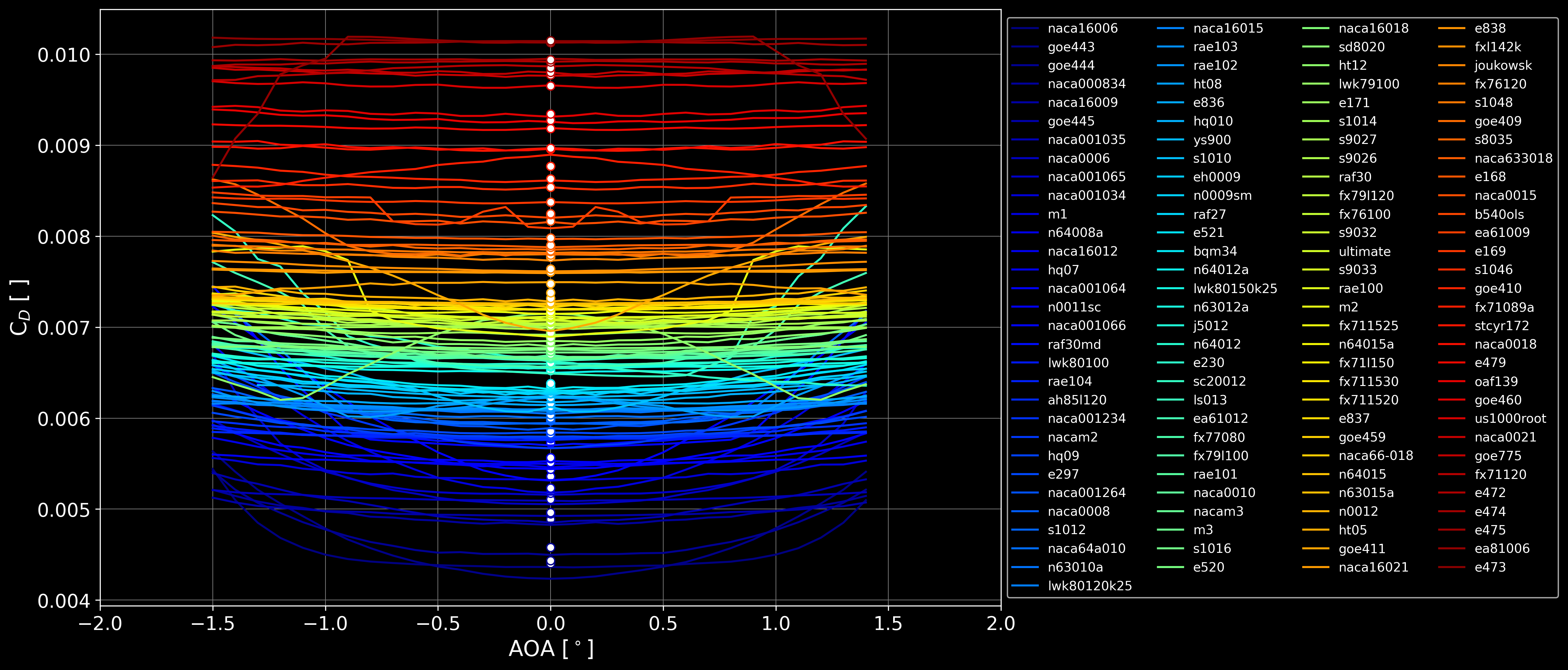
Average drag (Cd) over AOA
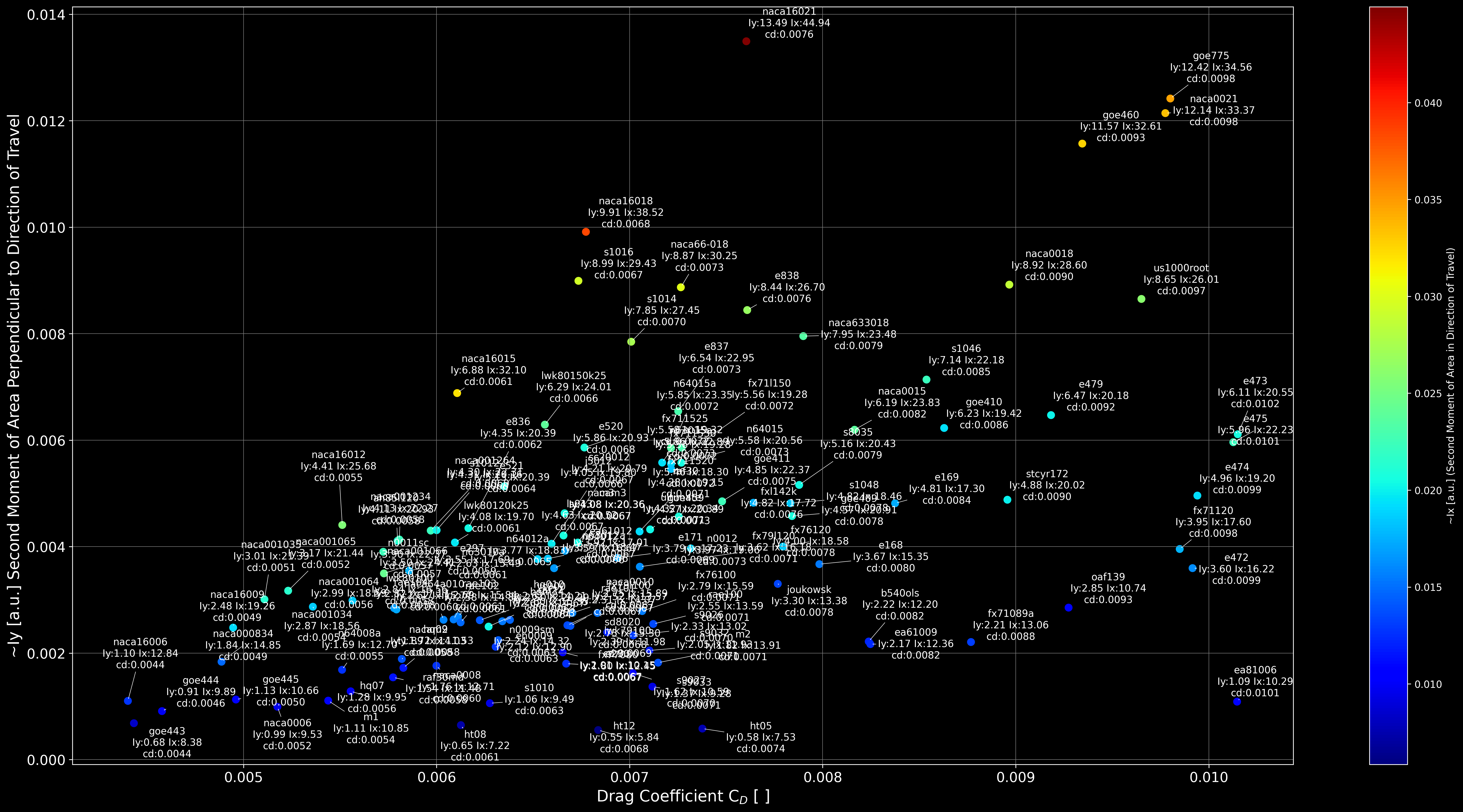
Second moments of area (Iy, Ix) over average drag (Cd) for all simulated profiles
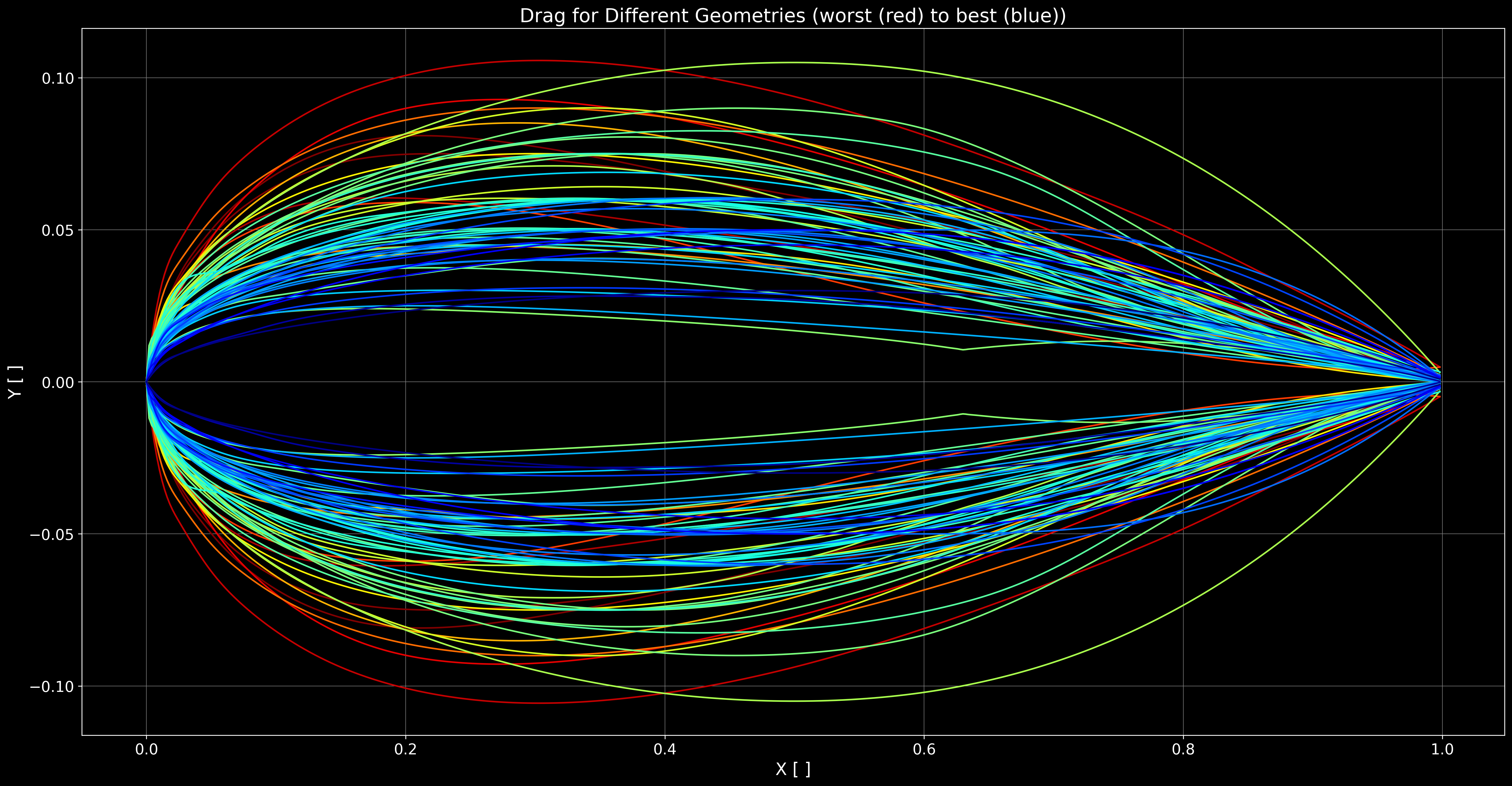
Average drag (Cd) for different geometries
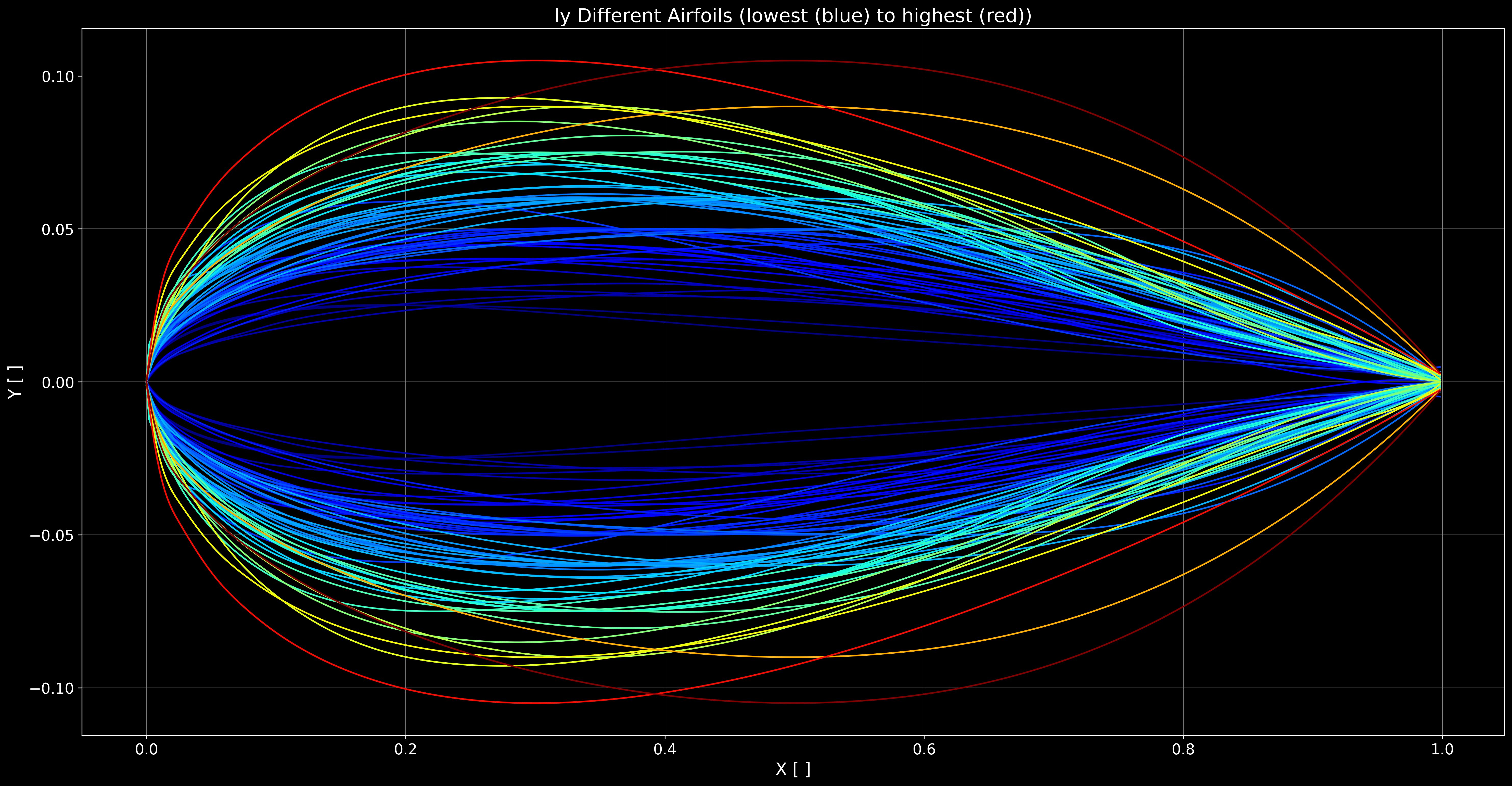
Second moments of area perpendicular to direction of motion (Iy) for different geometries
Get it running with a virtual environment:
Get the code from GitHub:
git clone https://github.com/cdorfer/hydrofoil-profile-selection.git
Create a virtual environment and install dependencies (Python 3.8 for sure works, if you get it to work on a more current version please open a pull request):
virtualenv -p /usr/bin/python3.8 py38
source py38/bin/activate
pip install -r requirements.txt
Fix parameters for your design. For my pumpoiling mast those would be:
* 20 km/h speed
* profile: symmetric
* average sumberged cord length: ~125 mm
* average submerged mast thickness: ~14 mm (Armstrong's 100 cm mast is 15 mm, Sabfoil uses ~14 mm, Axis' 19 mm aluminum mast is definitely too thick)
Get all symmetric profiles that roughly have the right chord length to thickness ratio from online database (or parameterize some yourself)
An airfoil database like for example airfoiltools.com can be searched for profiles with 0% camber (symmetrical profile) between a minimum and maximum thickness to length ratio. 14 mm / 125 mm = ~11.2% so let's consider profile between 10 - 12.5%. For a deep tuttle mast that goes flush into the box the limiting factor would be the 16 mm width at the box with a chord length of roughly 156 mm, thus about 10.25%. Alternatively the mast can be constructed similar to the 'Slingshot Ghost Whisperer' deep tuttle windfoil mast where the profile protrudes the deep tuttle. This however leaves pressure marks on your board if tolerances are not perfect.
Use airfoiltools_fetching/extract_links_for_search.py to generate a list of URLs to potential profiles (adapt search link to your needs).
Use airfoiltools_fetching/download_files.py to actually download a .dat file for each profile. Not all .dat files work out of the box in the simulation because their point cloud coordinate sets follow different standards (or they are not closed curves). Use the ones in the profiles_to_consider directory for your first attempts, they should do ok.
Run simulation
To calculate the lift/drag/momentum,etc. of each profile in profiles_to_consider first adapt the parameters chord_length_m and flow_speed_m_s in run_sim.py and then run it. This will loop through all profiles, run the viiflow simulation for them and dump the results in a pickle file results.pkl). On a newer desktop machine the calculations take ~3 seconds per profile.
How to select the best profile?
For me maximum rigidity against bending and torsion at the lowest drag value is 'the best', you might disagree - if so adapt the code accordingly.
Compare profiles and decide
The deflection of a mast when under load is inversely proportional to Young's modulus and the second moment of area which is solely a function of airfoil geometry. Young's modulus is defined as stress over strain i.e. loading applied over change in length and can only be increased by using higher modulus carbon in the build. So basically the higher the modulus the thinner the mast can be at the same stiffness. Many companies tout their use of 'ultra high modulus', '12K' but as the modulus of carbon fiber increases so does price, also the tensile strength reduces. That means that the mast might be super stiff but is also more likely to explode under excessive load or impact. Thus for any DIY mast planning it a few milimeters thicker than what is on the market is a reasonable approach (not one I took here of course ¯\_(ツ)_/¯ ).
The second moment of area can be calculated as shown on this Wikipedia page. Basically it is the distance of a finite mast hull shell squared times the area integrated over the whole length of the mast. In my simplification the must hull is infinitely thin. That way I can just integrate the squared distance between the hull and the center line (y=0) over the length of the chord [0,1]. This number is still proportional to what we want to know but not quantitative.
Running compare.py extracts the results from results.pkl, calculates the average coefficient of drag (c_d) between -1 and +1 degree AOA and plots it over AOA, second moments of area perpendicular to and parallel to the direction of travel for all simulated profiles. With that information it's up to you to decide which profile fits your needs the best.
Good luck!
Loved this?
Sign up to follow this builder and never miss an update.
Comments